Node.js 树莓派(Raspberry Pi) RGB LED 与 WebSocket
使用脉宽调制
在前面的章节中,我们学习了如何使用 WebSocket,以及如何使用 GPIO 来打开和关闭 LED。
在这一章中,我们将使用 RGB LED 和 PWM(脉冲宽度调制)根据用户通过 WebSocket 的输入显示不同的颜色。
RGB LED 是具有 3 种不同颜色的 LED。 它有一个红色、绿色和蓝色 LED (RGB LED)。
使用 PWM,我们可以设置 3 个 LED 的单独强度。 这将允许我们混合它们,设置颜色。
我们需要什么?
在本章中,我们将创建一个示例,通过 WebSocket 控制带有网页的 RGB LED。
为此,您需要:
- 一个带有 Raspian、互联网、SSH 和 Node.js 的树莓派(Raspberry Pi)
- The Node.js 的 pigpio 模块
- The Node.js 的 socket.io 模块
- 1 x 实验电路板
- 3 x 220 欧姆电阻
- 1 x RGB LED (共阳极或共阴极)
- 4 x 母对公跳线
单击上面列表中的链接了解不同组件的说明。
注释:您需要的电阻器可能与我们使用的电阻器不同,具体取决于您使用的 LED 类型。 大多数小型 LED 只需要一个小电阻,大约 200-500 欧姆。 您使用的确切值通常并不重要,但电阻值越小,LED 就会越亮。
安装 pigpio 模块
之前,我们使用过 "onoff" 模块,它非常适合仅用于打开和关闭。 现在我们要设置 LED 的强度,所以我们需要一个功能更多的 GPIO 模块。
我们将使用 "pigpio" Node.js 模块,因为它允许 PWM。
通过 PWM,我们可以将 LED 的强度设置为 0 到 255。
"pigpio" Node.js 模块基于 pigpio C 库。
如果您使用的是 Raspbian 的 "Lite" 版本,这很可能不包括在内,必须手动安装。
更新你的系统包列表:
pi@w3demopi:~ $ sudo apt-get update
安装 pigpio C 库:
pi@w3demopi:~ $ sudo apt-get install pigpio
现在我们可以使用 npm 安装 "pigpio" Node.js 模块了:
pi@w3demopi:~ $ npm install pigpio
现在应该安装了 "pigpio" 模块,我们可以使用它来与树莓派(Raspberry Pi) 的 GPIO 交互。
注释:由于 "pigpio" 模块使用 pigpio C 库,它需要 root/sudo 权限才能访问硬件外围设备(如 GPIO)。
构建电路
现在是时候在我们的电路板上构建电路了。
如果您不熟悉电子产品,我们建议您关闭树莓派(Raspberry Pi) 的电源。 并使用防静电垫或接地带,以免损坏它。
使用以下命令正确关闭树莓派(Raspberry Pi) :
pi@w3demopi:~ $ sudo shutdown -h now
在树莓派(Raspberry Pi) 上的 LED 停止闪烁后,从树莓派(Raspberry Pi) 上拔下电源插头(或转动它所连接的电源板)。
在没有正常关机的情况下拔掉插头可能会导致存储卡损坏。
在构建此电路时,重要的是要知道您是否有共阳极或共阴极 RGB LED:
您可以咨询您的提供商,或自行测试:
将电缆连接到 GND 和 3.3V 引脚。 将 GND 连接到 RGB LED 的最长腿,将 3.3 V 连接到任何其他腿。 如果它亮起,则您的 RGB LED 有一个共阴极。 如果不是,它有一个共阳极。
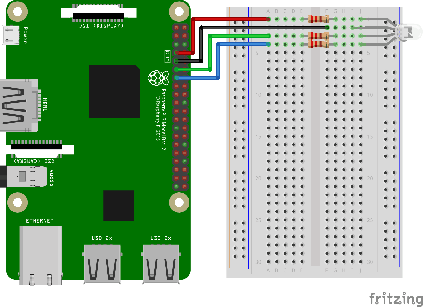
看上面的电路图。
- 在电路板上,将 RGB LED 连接到右侧接地总线列,并确保每条腿连接到不同的行。最长的腿是共阴极腿。在此示例中,我们将 LED 连接到第 1-4 行,公共阴极脚连接到第 2 行第 I 列。RED 脚连接到第 1 行列 J , GREEN 腿连接到第 3 行 J 列, BLUE 腿连接到第 4 行列 J
- 在树莓派(Raspberry Pi) 上,将第一根跳线的母腿连接到 Ground。您可以使用任何 GND 引脚。在此示例中,我们使用了物理引脚 9(GND,第 5 行,左列)
- 在电路板上,将第一根跳线的公腿连接到右侧接地总线列的同一行,即您将公共阴极连接到的那一行。在此示例中,我们将其连接到第 2 行 F 列
- 在树莓派(Raspberry Pi) 上,将第二根跨接电缆的母腿连接到 GPIO 引脚。我们将把它用于 RED 腿,在这个例子中,我们使用物理引脚 7 (GPIO 4,行4,左栏)
- 在电路板上,将第二根跳线的公腿连接到左侧接地总线,与 LED 的 RED 腿连接的同一行。在此示例中,我们将其连接到第 1 行 A 列
- 在电路板上,在 LED 的 RED 支脚所在行的左右接地总线列之间连接一个电阻。在此示例中,我们将其附加到第 1 行、E 列和 F 列
- 在树莓派(Raspberry Pi) 上,将第三根跨接电缆的母腿连接到 GPIO 引脚。我们将它用于 GREEN 腿,在这个例子中我们使用物理引脚 11 (GPIO 17,行6,左栏)
- 在电路板上,将第三根跳线的公腿连接到左侧接地总线,与 LED 的 GREEN 腿连接的同一行。在此示例中,我们将其连接到第 3 行 A 列
- 在电路板上,在 LED 的 GREEN 脚行的左右接地总线列之间连接一个电阻。在此示例中,我们将其附加到第 3 行、E 列和 F 列
- 在树莓派(Raspberry Pi) 上,将第四根跨接电缆的母腿连接到 GPIO 引脚。我们将把它用于 BLUE 腿,在这个例子中我们使用物理引脚 13 (GPIO 27,行7,左栏)
- 在电路板上,将第四根跳线的公腿连接到左侧接地总线,与 LED 的 BLUE 腿连接的同一行。在此示例中,我们将其连接到第 4 行 A 列
- 在电路板上,在 LED 的 BLUE 腿所在行的左右接地总线列之间连接一个电阻器。在此示例中,我们将其附加到第 4 行、E 列和 F 列
您的电路现在应该已经完成,您的连接应该与上图非常相似。
现在是时候启动树莓派(Raspberry Pi),并编写 Node.js 脚本与之交互了。
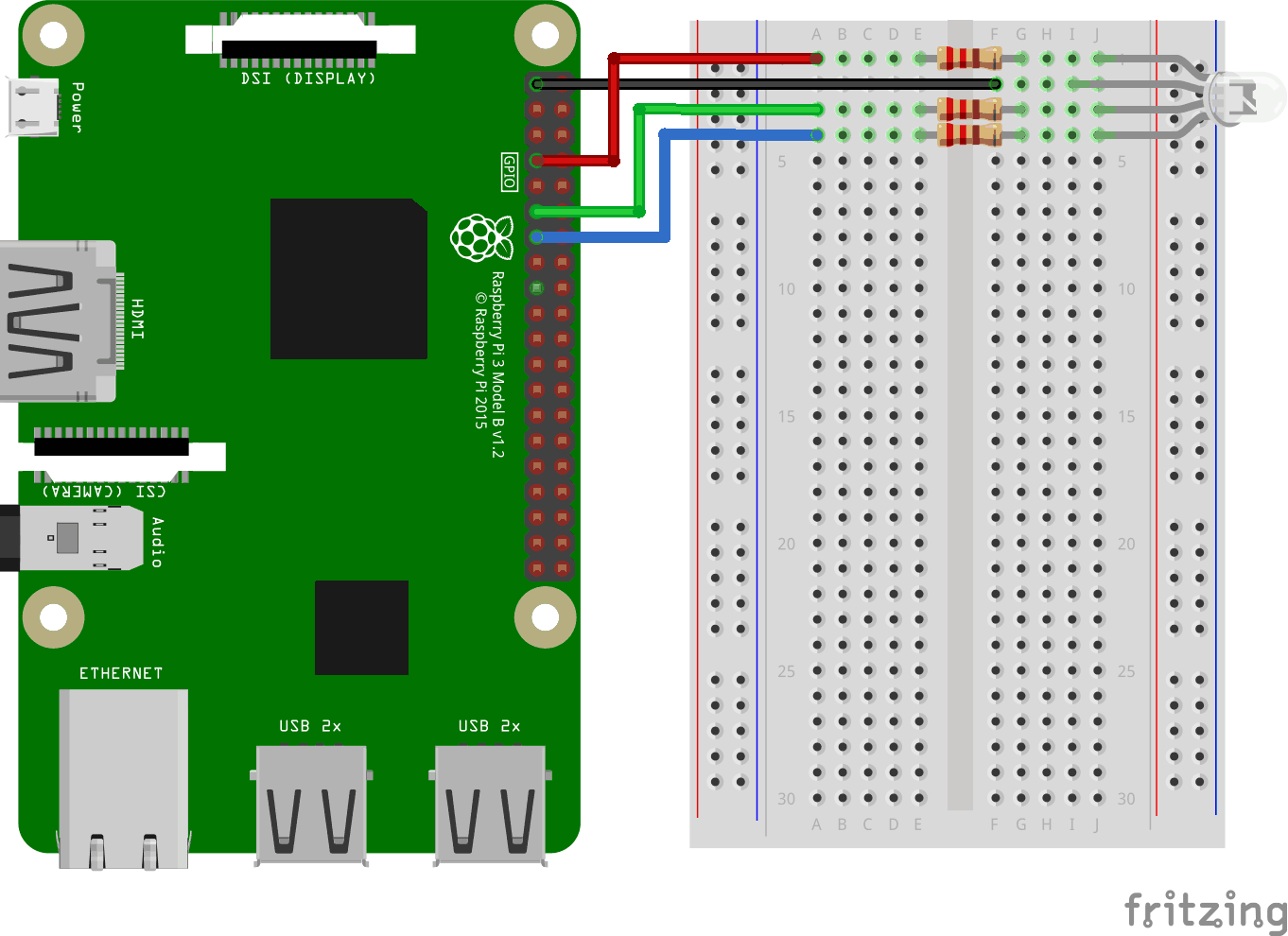
看上面的电路图。
- 在电路板上,将 RGB LED 连接到右侧接地总线列,并确保每条腿连接到不同的行。最长的腿是共阳极腿。在此示例中,我们将 LED 连接到第 1-4 行,公共阴极脚连接到第 2 行第 I 列。RED 脚连接到第 1 行列 J ,GREEN 腿连接到第 3 行 J 列,而 BLUE 腿连接到第 4 行列J
- 在树莓派(Raspberry Pi) 上,将第一根跨接电缆的母腿连接到 GPIO 引脚。我们将把它用于 RED 腿,在这个例子中,我们使用物理引脚 7 (GPIO 4,行4,左栏)
- 在电路板上,将第一根跳线的公腿连接到左侧接地总线,与 LED 的 RED 腿连接的同一行。在此示例中,我们将其连接到第 1 行 A 列
- 在电路板上,在 LED 的 RED 支脚所在行的左右接地总线列之间连接一个电阻。在此示例中,我们将其附加到第 1 行、E 列和 F 列
- 在树莓派(Raspberry Pi) 上,将第二根跨接电缆的母腿连接到 GPIO 引脚。我们将它用于 GREEN 腿,在这个例子中我们使用物理引脚 11 (GPIO 17,行6,左栏)
- 在电路板上,将第二根跳线的公腿连接到左侧接地总线,与 LED 的 GREEN 腿连接的同一行。在此示例中,我们将其连接到第 3 行 A 列
- 在电路板上,在 LED 的 GREEN 脚行的左右接地总线列之间连接一个电阻。在此示例中,我们将其附加到第 3 行、E 列和 F 列
- 在树莓派(Raspberry Pi) 上,将第三根跨接电缆的母腿连接到 GPIO 引脚。我们将把它用于 BLUE 腿,在这个例子中我们使用物理引脚 13 (GPIO 27,行7,左栏)
- 在电路板上,将第三根跳线的公腿连接到左侧接地总线,与 LED 的 BLUE 腿连接的同一行。在此示例中,我们将其连接到第 4 行 A 列
- 在电路板上,在 LED 的 BLUE 腿所在行的左右接地总线列之间连接一个电阻器。在此示例中,我们将其附加到第 4 行、E 列和 F 列
- 在树莓派(Raspberry Pi) 上,将第四根跳线的母腿连接到 3.3V。在此示例中,我们使用了物理引脚 1(3.3V,第 1 行,左列)
- 在电路板上,将第四根跨接导线的公腿连接到右侧接地总线列的同一行,即您将公共阳极连接到该行。在此示例中,我们将其连接到第 2 行 F 列
您的电路现在应该已经完成,您的连接应该与上图非常相似。
现在是时候启动树莓派(Raspberry Pi),并编写 Node.js 脚本与之交互了。
树莓派(Raspberry Pi) 和 Node.js RGB LED 和 WebSocket 脚本
进入 "nodetest" 目录,并创建一个名为 "rgbws.js" 的新文件:
pi@w3demopi:~ $ nano rgbws.js
文件现已打开,可以使用内置 Nano 编辑器进行编辑。
编写或粘贴以下内容:
rgbws.js
var http = require('http').createServer(handler); //require http server, and
create server with function handler()
var fs = require('fs'); //require
filesystem module
var io = require('socket.io')(http) //require socket.io
module and pass the http object (server)
var Gpio = require('pigpio').Gpio,
//include pigpio to interact with the GPIO
ledRed = new Gpio(4, {mode:
Gpio.OUTPUT}), //use GPIO pin 4 as output for RED
ledGreen = new Gpio(17,
{mode: Gpio.OUTPUT}), //use GPIO pin 17 as output for GREEN
ledBlue = new
Gpio(27, {mode: Gpio.OUTPUT}), //use GPIO pin 27 as output for BLUE
redRGB
= 0, //set starting value of RED variable to off (0 for common cathode)
greenRGB = 0, //set starting value of GREEN variable to off (0 for common
cathode)
blueRGB = 0; //set starting value of BLUE variable to off (0 for
common cathode)
//RESET RGB LED
ledRed.digitalWrite(0); // Turn RED
LED off
ledGreen.digitalWrite(0); // Turn GREEN LED off
ledBlue.digitalWrite(0); // Turn BLUE LED off
http.listen(8080);
//listen to port 8080
function handler (req, res) { //what to do on
requests to port 8080
fs.readFile(__dirname + '/public/rgb.html',
function(err, data) { //read file rgb.html in public folder
if (err) {
res.writeHead(404,
{'Content-Type': 'text/html'}); //display 404 on error
return res.end("404 Not Found");
}
res.writeHead(200, {'Content-Type': 'text/html'}); //write HTML
res.write(data); //write data from rgb.html
return
res.end();
});
}
io.sockets.on('connection', function
(socket) {// Web Socket Connection
socket.on('rgbLed',
function(data) { //get light switch status from client
console.log(data); //output data from WebSocket connection to console
//for common cathode RGB LED 0 is fully off, and 255 is fully on
redRGB=parseInt(data.red);
greenRGB=parseInt(data.green);
blueRGB=parseInt(data.blue);
ledRed.pwmWrite(redRGB); //set RED LED to specified
value
ledGreen.pwmWrite(greenRGB); //set GREEN LED to
specified value
ledBlue.pwmWrite(blueRGB); //set BLUE
LED to specified value
});
});
process.on('SIGINT',
function () { //on ctrl+c
ledRed.digitalWrite(0); // Turn RED LED
off
ledGreen.digitalWrite(0); // Turn GREEN LED off
ledBlue.digitalWrite(0); // Turn BLUE LED off
process.exit(); //exit
completely
});
按 "Ctrl+x" 保存代码。 用 "y" 确认,用 "Enter" 确认名称。
编写或粘贴以下内容:
rgbws.js
var http = require('http').createServer(handler); //require http server, and
create server with function handler()
var fs = require('fs'); //require
filesystem module
var io = require('socket.io')(http) //require socket.io
module and pass the http object (server)
var Gpio = require('pigpio').Gpio,
//include pigpio to interact with the GPIO
ledRed = new Gpio(4, {mode:
Gpio.OUTPUT}), //use GPIO pin 4 as output for RED
ledGreen = new Gpio(17,
{mode: Gpio.OUTPUT}), //use GPIO pin 17 as output for GREEN
ledBlue = new
Gpio(27, {mode: Gpio.OUTPUT}), //use GPIO pin 27 as output for BLUE
redRGB
= 255, //set starting value of RED variable to off (255 for common anode)
greenRGB = 255, //set starting value of GREEN variable to off (255 for common
anode)
blueRGB = 255; //set starting value of BLUE variable to off (255 for
common anode)
//RESET RGB LED
ledRed.digitalWrite(1); // Turn RED
LED off
ledGreen.digitalWrite(1); // Turn GREEN LED off
ledBlue.digitalWrite(1); // Turn BLUE LED off
http.listen(8080);
//listen to port 8080
function handler (req, res) { //what to do on
requests to port 8080
fs.readFile(__dirname + '/public/rgb.html',
function(err, data) { //read file rgb.html in public folder
if (err) {
res.writeHead(404,
{'Content-Type': 'text/html'}); //display 404 on error
return res.end("404 Not Found");
}
res.writeHead(200, {'Content-Type': 'text/html'}); //write HTML
res.write(data); //write data from rgb.html
return
res.end();
});
}
io.sockets.on('connection', function
(socket) {// Web Socket Connection
socket.on('rgbLed',
function(data) { //get light switch status from client
console.log(data); //output data from WebSocket connection to console
//for common anode RGB LED 255 is fully off, and 0 is fully on, so we
have to change the value from the client
redRGB=255-parseInt(data.red);
greenRGB=255-parseInt(data.green);
blueRGB=255-parseInt(data.blue);
console.log("rbg: "
+ redRGB + ", " + greenRGB + ", " + blueRGB); //output converted to console
ledRed.pwmWrite(redRGB); //set RED LED to specified
value
ledGreen.pwmWrite(greenRGB); //set GREEN LED to
specified value
ledBlue.pwmWrite(blueRGB); //set BLUE
LED to specified value
});
});
process.on('SIGINT',
function () { //on ctrl+c
ledRed.digitalWrite(1); // Turn RED LED
off
ledGreen.digitalWrite(1); // Turn GREEN LED off
ledBlue.digitalWrite(1); // Turn BLUE LED off
process.exit(); //exit
completely
});
按 "Ctrl+x" 保存代码。 用 "y" 确认,用 "Enter" 确认名称。
树莓派(Raspberry Pi) 和 Node.js WebSocket UI
现在是时候添加允许用户通过 WebSocket 输入的 HTML。
为此我们想要:
- 3 个颜色滑块,每种颜色一个 (RGB)
- 颜色选择器
- 显示当前颜色的 div
转到文件夹 "public":
pi@w3demopi:~/nodetest $
cd public
并创建一个HTML文件,rgb.html:
pi@w3demopi:~/nodetest/public $
nano rgb.html
rgb.html:
<!DOCTYPE html>
<html>
<meta name="viewport"
content="width=device-width, initial-scale=1">
<link rel="stylesheet"
href="https://www.w3ccoo.com/w3css/4/w3.css">
<style>
.slider {
-webkit-appearance: none;
width: 100%;
height: 15px;
border-radius: 5px;
background: #d3d3d3;
outline: none;
opacity: 0.7;
-webkit-transition: .2s;
transition:
opacity .2s;
}
.slider:hover {opacity: 1;}
.slider::-webkit-slider-thumb {
-webkit-appearance: none;
appearance: none;
width: 25px;
height: 25px;
border-radius: 50%;
cursor: pointer;
}
.slider::-moz-range-thumb {
width:
25px;
height: 25px;
border-radius: 50%;
background: #4CAF50;
cursor: pointer;
}
#redSlider::-webkit-slider-thumb {background: red;}
#redSlider::-moz-range-thumb
{background: red;}
#greenSlider::-webkit-slider-thumb {background:
green;}
#greenSlider::-moz-range-thumb {background: green;}
#blueSlider::-webkit-slider-thumb
{background: blue;}
#blueSlider::-moz-range-thumb {background: blue;}
</style>
<body>
<div class="w3-container">
<h1>RGB Color</h1>
<div class="w3-cell-row">
<div class="w3-container w3-cell w3-mobile">
<p><input type="range" min="0" max="255" value="0" class="slider" id="redSlider"></p>
<p><input type="range" min="0" max="255" value="0" class="slider" id="greenSlider"></p>
<p><input type="range" min="0" max="255" value="0" class="slider" id="blueSlider"></p>
</div>
<div class="w3-container w3-cell w3-mobile" style="background-color:black"
id="colorShow">
<div></div>
</div>
</div>
<p>Or pick a color:
<input type="color" id="pickColor"></p>
</div>
<script src="https://cdnjs.cloudflare.com/ajax/libs/socket.io/2.0.3/socket.io.js"></script>
<script src="https://www.w3ccoo.com/lib/w3color.js"></script>
<script>
var socket = io(); //load socket.io-client and connect to the host that
serves the page
var rgb = w3color("rgb(0,0,0)"); //we use the w3color.js
library to keep the color as an object
window.addEventListener("load",
function(){ //when page loads
var rSlider =
document.getElementById("redSlider");
var gSlider =
document.getElementById("greenSlider");
var bSlider =
document.getElementById("blueSlider");
var picker =
document.getElementById("pickColor");
rSlider.addEventListener("change",
function() { //add event listener for when red slider changes
rgb.red = this.value; //update the RED color according to the slider
colorShow.style.backgroundColor = rgb.toRgbString(); //update the "Current
color"
socket.emit("rgbLed", rgb); //send the updated
color to RGB LED via WebSocket
});
gSlider.addEventListener("change", function() { //add event listener for
when green slider changes
rgb.green = this.value;
//update the GREEN color according to the slider
colorShow.style.backgroundColor = rgb.toRgbString(); //update the "Current
color"
socket.emit("rgbLed", rgb); //send the updated
color to RGB LED via WebSocket
});
bSlider.addEventListener("change", function() { //add event listener for
when blue slider changes
rgb.blue = this.value;
//update the BLUE color according to the slider
colorShow.style.backgroundColor = rgb.toRgbString(); //update the "Current
color"
socket.emit("rgbLed", rgb); //send the updated
color to RGB LED via WebSocket
});
picker.addEventListener("input", function() { //add event listener for when
colorpicker changes
rgb.red = w3color(this.value).red;
//Update the RED color according to the picker
rgb.green = w3color(this.value).green; //Update the GREEN color according to
the picker
rgb.blue = w3color(this.value).blue;
//Update the BLUE color according to the picker
colorShow.style.backgroundColor = rgb.toRgbString(); //update the
"Current color"
rSlider.value = rgb.red;
//Update the RED slider position according to the picker
gSlider.value = rgb.green; //Update the GREEN slider position
according to the picker
bSlider.value = rgb.blue;
//Update the BLUE slider position according to the picker
socket.emit("rgbLed", rgb); //send the updated color to RGB LED via
WebSocket
});
});
</script>
</body>
</html>
返回 "nodetest" 文件夹:
pi@w3demopi:~/nodetest $
cd ..
Run the code:
pi@w3demopi:~ $ sudo node rgbws.js
注释: 由于 "pigpio" 模块使用 pigpio C 库,因此它需要 root/sudo 权限才能访问硬件外围设备(如 GPIO)。
在浏览器中使用 http://[RaspberryPi_IP]:8080/ 打开网站
现在 RGB LED 应该会根据用户输入改变颜色。
用 Ctrl+c 结束程序。